使用思科Cisco Packet Tracer创建一个简单的网络
Cisco Packet Tracer是由思科系统设计的跨平台可视化仿真工具。它允许用户创建网络拓扑以模仿计算机网络。在本文种我们将介绍怎么使用Cisco Packet Tracer创建一个简单网络
Packet Tracer是由思科系统设计的跨平台可视化仿真工具,它允许用户创建网络拓扑以模仿计算机网络和使用命令行界面来模拟配置思科路由器和交换机。Packet Tracer的用户界面为拖放式,允许用户根据自己的需要添加和删除模拟的网络设备。该软件主要面向参加思科认证网络工程师认证考试的学生,作为他们备考思科认证网络工程师认证考试的学习工具。
在本文中我们将介绍怎么使用Cisco Packet Tracer创建一个简单网络,我们还将解释每个命令含义,除了要使用的命令外,我们还介绍一些其它的命令。如果你经常使用Linux,这些命令可能对你来说非常简单的。我们并不用刻意去记住它。
先决条件
在查看本文前你必须具备以下基础的网络知识
- 了解交换机与路由器作用
- 了解组建网络IP与子网掩码的作用
下载安装Cisco Packet Tracer
点击链接下载并安装Cisco Packet Tracer。这个下载链接种包含了Linux,Windows,Mac的安装包,请选择适合自己平台进行安装。
Linux安装Cisco Packet Tracer
sudo dpkg -i PacketTracer_730_amd64.debWindows与Mac安装Cisco Packet Tracer
请自行点击“下一步”进行安装。这里不再描述
构建一个简单网络拓扑
现在我们开始创建一个简单网络基础,我们将会学习如何使两个不同网段进行通讯。下面是我们网络拓扑图。
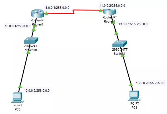
这个网络拓补包含了连个PC,交换机,路由器并划分3个网段。接下来,我们为这些配置IP,网关,子网掩码。你也许可能会知道这里的PC可以是可以不用配置IP,网关,子网掩码。但在这里我们暂时不设置动态获取,而是全程手动配置,可以学习更多。
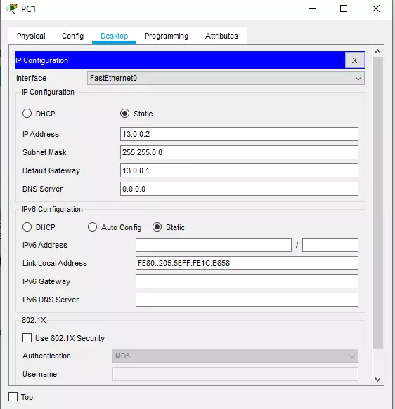
为计算机配置IP,网关,子网掩码
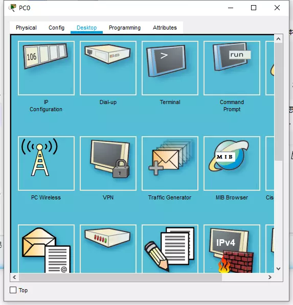
要为计算机PC配置IP,网关,子网掩码。直接点击PC1或者PC1,我们将看到以下对话框,然后点击Desktop,点击IP Configure
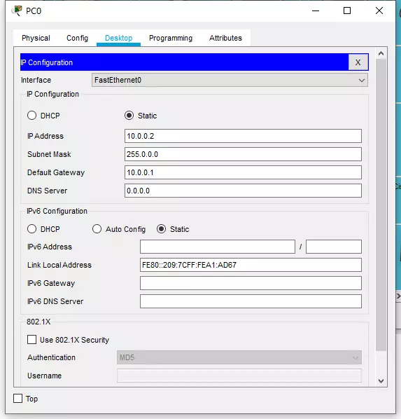
配置PC0的IP,网关,子网掩码
现在我们已经为计算机配置了IP,网关,子网掩码。接下来我们为路由器配置IP以及路由表。众所周知,企业级路由器都没有GUI接口,这是为了保证路由器稳定性,内存使用而考虑而牺牲掉的。
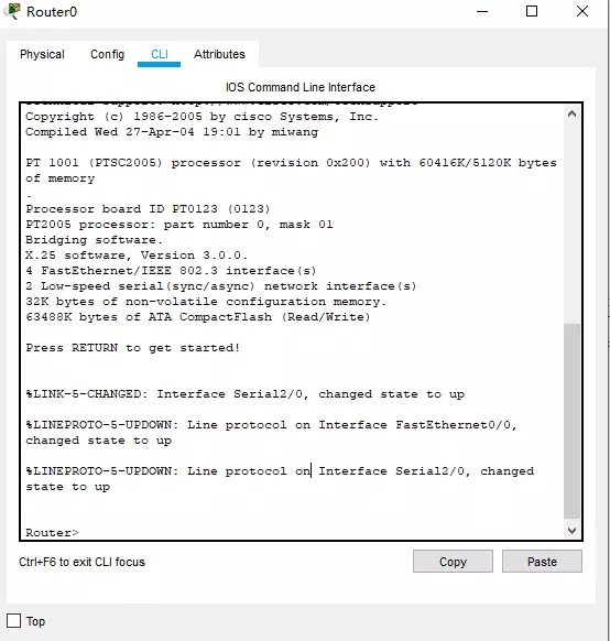
为路由器配置IP以及路由表
点击路由器->CLI,并将光标放到命令行接口框种,接着按回车键。我们将会看到以下对话框
在路由器中,我们需要配置两个端口,一个是针对10.0.0.1/255.0.0.0网段接口,一个连接到下一个路由器的接口11.0.0.1/255.0.0.0 。
路由器serial 2/0接口11.0.0.1/255.0.0.0
enable #进入特权模式
configure terminal #进入配置模式
interface serial 2/0 #选择serial 2/0接口
ip address 11.0.0.1 255.0.0.0 #配置IP,子网掩码
no shutdown # 启用这个接口
end #退出配置模式
show ip interface serial 2/0 #显示serial 2/0接口信息,输出如下Serial2/0 is up, line protocol is up (connected)
Internet address is 11.0.0.1/8
Broadcast address is 255.255.255.255
Address determined by setup command
MTU is 1500
Helper address is not set
Directed broadcast forwarding is disabled
Outgoing access list is not set
Inbound access list is not set
Proxy ARP is enabled
Security level is default
Split horizon is enabled
ICMP redirects are always sent
ICMP unreachables are always sent
ICMP mask replies are never sent
IP fast switching is disabled
IP fast switching on the same interface is disabled
IP Flow switching is disabled
IP Fast switching turbo vector
IP multicast fast switching is disabled
IP multicast distributed fast switching is disabled
Router Discovery is disabled
IP output packet accounting is disabled
IP access violation accounting is disabled
TCP/IP header compression is disabled
RTP/IP header compression is disabled
Probe proxy name replies are disabled
Policy routing is disabled
Network address translation is disabled
WCCP Redirect outbound is disabled
WCCP Redirect exclude is disabled
BGP Policy Mapping is disabled现在,我们已经看到serial 2/0接口的IP地址是我们所设置的IP地址。接下来我们设置Router0的在10.0.0.1/255.0.0.0网段上的接口
路由器serial 2/0接口11.0.0.1/255.0.0.0
enable #进入特权模式
configure terminal #进入配置模式
interface fastEthernet 0/0 #选择serial 2/0接口
ip address 10.0.0.1 255.0.0.0 #配置IP,子网掩码
no shutdown # 启用这个接口
end #退出配置模式
show ip interface fastEthernet 0/0 #fastEthernet 0/0接口信息,输出如下
FastEthernet0/0 is up, line protocol is up (connected)
Internet address is 10.0.0.1/8
Broadcast address is 255.255.255.255
Address determined by setup command
MTU is 1500 bytes
Helper address is not set
Directed broadcast forwarding is disabled
Outgoing access list is not set
Inbound access list is not set
Proxy ARP is enabled
Security level is default
Split horizon is enabled
ICMP redirects are always sent
ICMP unreachables are always sent
ICMP mask replies are never sent
IP fast switching is disabled
IP fast switching on the same interface is disabled
IP Flow switching is disabled
IP Fast switching turbo vector
IP multicast fast switching is disabled
IP multicast distributed fast switching is disabled
Router Discovery is disabled
IP output packet accounting is disabled
IP access violation accounting is disabled
TCP/IP header compression is disabled
RTP/IP header compression is disabled
Probe proxy name replies are disabled
Policy routing is disabled
Network address translation is disabled
BGP Policy Mapping is disabled
Input features: MCI Check
WCCP Redirect outbound is disabled
WCCP Redirect inbound is disabled
WCCP Redirect exclude is disabled
现在,我们已经设置完Router0的配置,至于Router1这里不再描述,与操作Router0命令类似,只需要把接口,IP地址改一下即可。那么接下来我们需要验证路由器是否正常的连接
Router#ping 11.0.0.2
输出如下

Type escape sequence to abort.
Sending 5, 100-byte ICMP Echos to 11.0.0.2, timeout is 2 seconds:
!!!!!
Success rate is 100 percent (5/5), round-trip min/avg/max = 7/8/12 ms
配置路由表
路由表为当前路由指示着下一跳可以到那个网段,它是跨网段通讯的桥梁。路由表可以是静态或者动态的,动态的路由表,即路由自己发现下一跳路由地址与网段,不需要手动添加,这里我们将设置静态路由表,学习如何添加路由到路由表。点击路由器Router0>CLI
enable #进入特权模式
configure terminal #进入配置模式
ip route 13.0.0.0 255.255.0.0 11.0.0.2
exit
ip route 13.0.0.0 255.255.0.0 11.0.0.2 这里说说这个命令含义,ip route即添加路由,13.0.0.0 255.255.0.0 指示着下一个网段,11.0.0.2 下一跳的路由器的IP地址。整体来说就是告知路由器Router0可以在11.0.0.2 路由器到达13.0.0.0 255.255.0.0 网段
验证路由表是否已经添加
Router#show ip route
Codes: C - connected, S - static, I - IGRP, R - RIP, M - mobile, B - BGP
       D - EIGRP, EX - EIGRP external, O - OSPF, IA - OSPF inter area
       N1 - OSPF NSSA external type 1, N2 - OSPF NSSA external type 2
       E1 - OSPF external type 1, E2 - OSPF external type 2, E - EGP
       i - IS-IS, L1 - IS-IS level-1, L2 - IS-IS level-2, ia - IS-IS inter area
       * - candidate default, U - per-user static route, o - ODR
       P - periodic downloaded static route

Gateway of last resort is not set

C    10.0.0.0/8 is directly connected, FastEthernet0/0
C    11.0.0.0/8 is directly connected, Serial2/0
     13.0.0.0/16 is subnetted, 1 subnets
S       13.0.0.0 [1/0] via 11.0.0.2  #前面的S代表静态理由即Codes的S - static
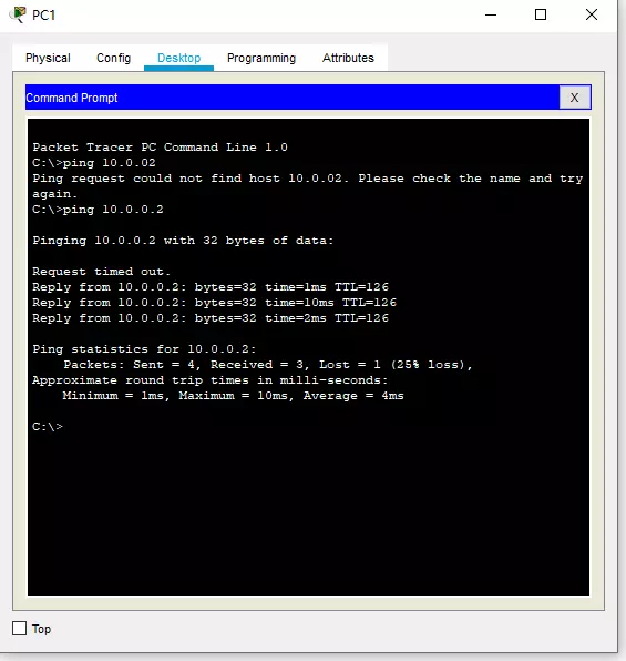
正常的连接如上面所示,那么我么们接下来看看计算机是否可以ping同。
结论
至此,你已经了解Cisco Packet Tracer的用法以及了解如何在Cisco Packet Tracer创建一个跨网段通讯网络。如果你对Cisco Packet Tracer感兴趣可以在思科的网络课程中找到文档与教程